| |
|
|
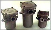
Hydraulic Accessories
|
|
|
| |
|
|
|
|
|
| |
|
|
MODEL |
DESPALCMENT |
RATING MICRON |
A |
B |
C |
D |
E |
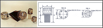
FSB-5 (Steel / Nylon Filter) |
5 CFM/150 LPM |
40 |
45 |
52 |
63 |
28 |
115 |
FSB-25 (Steel / Nylon Filter) |
25 CFM/720 LPM |
40 |
76.2 |
63 |
87 |
49.2 |
150 |
|
|
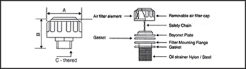
MODEL |
DESPALCMENT |
RATING MICRON |
TB-5 |
5 CFM/150 LPM |
40 |
TB-25 |
25 CFM/720 LPM |
40 |
DIMENSION IN MM ARE FOR REFERENCE ONLY |
|
| |
|
|
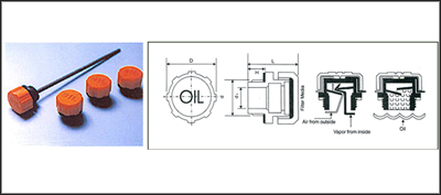
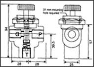
Brethers Plugs With Splash Guard Tbp : |
|
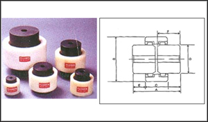
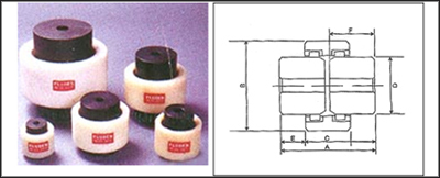
Gear Coupling |
| |
|
|
|
|
|
| |
|
|
 pecial polyamide technopolymer orange cover marked "OIL" black thread connector, Resistant to solvents, Oil, Greases and other Chemical agents.
Flat NBR synthetic packing ring.
Maximum temperature 120ºC.
Type TBP with "Foam" air filter, air filtration 40 Microns.
TBP breather Plugs come complete with splash guard device that prevents oil loss.
Especially suitable for use where oil is agitated violently and could be splashed against breather cap.
Standard Element |
Main Dimensions |
Weight |
Description |
d |
H |
D |
L |
d2 |
Grams |
TBP 30 16 X 1.5
TBP 30 18 X 1.5
TBP 30 20 X 1.5
TBP 30 22 X 1.5 |
M16 X 1.5
M18 X 1.5
M20 X 1.5
M22 X 1.5 |
10 |
31 |
30 |
10
10
12
12 |
10
10
11
11 |
TBP 30 – ¼
TBP 30 – 3/8
TBP 30 – ½ |
¼ Gas
3/8 Gas
½ Gas |
10 |
31 |
30 |
8
10
12 |
10
11
11 |
TBP 40 – 3/8
TBP 40 – ½
TBP 40 – ¾
TBP 40 - 1 |
3/8 Gas
½ Gas
¾ Gas
1 Gas |
12 |
42 |
37 |
10
12
18
23 |
20
22
22
22 |
TBP 57 – ¾
TBP 57 – 1
TBP 57 – 1 ¼
TBP 57-1 ½ |
¾ Gas
1 Gas
1¼ Gas
1 ½ Gas |
14
14
16
16 |
57 |
42
42
44
44 |
18
23
28
28 |
40
40
41
45 |
TBP 70-2 |
2 Gas |
17 |
70 |
59 |
23 |
82 |
DIMENSION IN MM ARE FOR REFERENCE ONLY |
|
|
Application to all range of hydraulic equipment and in the transmission market.
Maintenance free no lubrication crowned tooth form gear permitting axial and angular misalignment.
Cost effective, easy to assemble.
2 drive hubs engaging in a sleeve.
Compact and streamlined available in five sizes to suit 1 to 75 HP maximum.
Maximum permissible angular misalignment 1.5 degrees. Ensure coupling hubs easily fit on shaft. Do not use undue force. Maintain gap between hubs as shown in sketch. Use grub screws to locate gear hubs on their respective shafts. For shock load application use the following formula.
Rating / 100 RPM of coupling = Hp of application X 100 X F
__________________________
RPM of application
Ordering GDE |
M19mm |
M28mm |
M38mm |
M48mm |
M65mm |
| A |
54 |
81 |
84 |
110 |
144 |
| B |
48 |
66 |
85 |
100 |
140 |
| C |
37 |
46 |
48 |
53 |
72 |
| D |
30 |
44 |
58 |
65 |
96 |
| E |
8.5 |
19 |
18 |
29 |
36 |
| F |
25 |
40 |
40 |
54 |
70 |
| G Pilot Bore Dia |
10 |
13 |
15 |
17 |
20 |
|
Coupling Size |
Elec.Motor Frame Size |
3000 RPM |
1500 RPM |
1000 RPM |
750 RPM |
Max. Torque at
1500 RPM |
Max. RPM |
|
KW |
HP |
KW |
HP |
KW |
HP |
KW |
HP |
Kg. M |
Ft. Lbs |
|
19 |
80 90S 90L |
2.2 |
2 |
1.5 |
1 |
1.1 |
1 |
.75 |
1 |
.5 |
3.6 |
3000 |
|
28 |
100L 112M |
7.5 |
10 |
5.5 |
5 |
4.25 |
5 |
2.2 |
3 |
2.3 |
16.6 |
3000 |
|
38 |
132S 132 M |
10 |
13 |
7.5 |
10 |
5.5 |
7.5 |
3 |
4.5 |
7 |
4.9 |
3000 |
|
48 |
160ML 180ML |
22 |
30 |
18.5 |
25 |
15 |
20 |
11 |
15 |
14.4 |
104 |
3000 |
|
65 |
200L 250 M |
55 |
75 |
55 |
75 |
37 |
50 |
30 |
40 |
35.5 |
256 |
3000 |
|
All Dimensions are in mm. For reference only |
|
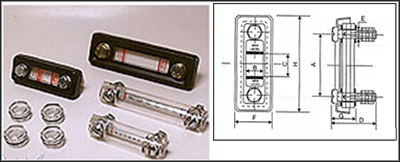
Level Gauge |
|
Knob Type Level Gauge :
|
| |
|
|
|
|
|
|
|
|
Face Type Level Gauge |
|
|
| |
|
|
A sturdy one piece construction, incorporating specially treated engineering plastic with fluden sealing arrangement. The Standard Supply of Units consists of 1 set of Bolts, Nuts, Plain Washer and 'O' ring completes for ready fitment anywhere by providing two holes. These are available in two sizes of 3" & 5" (3" & %" indicates the centre distance between the two dirlled holes).
These units are ideally suitable in petroleum/mineral based fluids in hydraulic reservior, Fuel Tanks, Drill Rig, Power Packs, Moulding Machines and other wide range of application to indicates the fluid levels as marked on the units.
These units are ideal for temperture up to 120°C and pressure up to 4 Kg./cm2. |
|
• Special transparent polyamide technopolymer Resistant to solvents, Oils with Additives,Greases, Acid and Alkali
• Avoid contact with Alcohol and Detergents containing Alcohol
• Anodized aluminum star-shaped contrast screen and cental level sight hole.
• NBR synthetic rubber packing ring Maximum working temperature 110 centigrade at normal pressure
Dimensional Details/ Ordering Information
| CODE |
d1 |
A |
B |
D |
d1 |
S |
Grams |
| Knob |
16 X 1.5 |
8 |
7 |
22 |
11 |
19 |
4 |
| Knob |
20 X 1.5 |
8 |
8 |
26 |
14 |
22 |
5 |
| Knob |
25 X 1.5 |
8 |
9 |
31 |
18 |
27 |
8 |
| Knob |
30 X 1.5 |
9 |
10 |
35 |
22 |
30 |
10 |
| Knob |
35 X 1.5 |
11 |
10 |
40 |
25 |
34 |
12 |
| Knob |
¼" BSP |
10 |
6 |
18 |
9 |
15 |
3 |
| Knob |
3/8" BSP |
8 |
7 |
22 |
11 |
19 |
4 |
| Knob |
½" BSP |
10 |
8 |
26 |
14 |
22 |
5 |
| Knob |
¾" BSP |
10 |
8 |
30 |
20 |
27 |
8 |
| Knob |
1" BSP |
11 |
10 |
40 |
25 |
34 |
12 |
| Knob |
1.¼" BSP |
12 |
13 |
47 |
30 |
41 |
20 |
DIMENSION IN MM ARE FOR REFERENCE ONLY |
|
These units can also be fitted externally by providing two tapped holes on reservior itself. |
|
| |
|
MODEL-2 |
A |
B |
C |
D |
E |
F |
FLG2-3 |
3" |
33 |
M-10 |
28 |
105 |
13 |
FLG2-5 |
5" |
33 |
M-10 |
28 |
160 |
13 |
DIMENSION IN MM ARE FOR REFERENCE ONLY |
|
|
| |
|
|
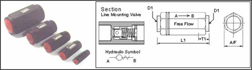
Check Valves : |
|
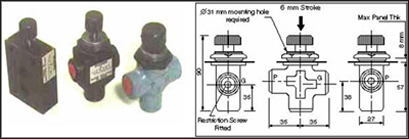
Gauge Isolator Valve : |
| |
|
|
Inline Check Valves : Technical Specification |
|
Model : FP 200/M |
| |
|
|
|
|
|
| |
|
|
• Construction -Seal Type
• Flow Direction- Free Flow from A toB Leakage free closure in opposite direction
• Mounting Style-Inline Mounting
• Viscosity Range-10 CST to 350 CST
• Hydrulic Medium-Mineral Oil
• Operating Pressure-315 Bar
• Fluid Temperature Range- 20 to +70 degree C
|
|
This push-to-read Gauge Isolator is designed for use with pressure gauges to prevent damage from shocks. The unit automatically vents the gauge to tank when a gauge reading is not required and considerable savings can be obtained on the life of the gauge and the most important factor, also preserving the accuracy of the gauge. The standard unit is designed basically panel mounting. The unit has a basic high grade alloy with hardened alloy spool and is suitable for working pressures up to 352 Kg/sq. cm.(5000 PSI). By using this type of Gauge Isolator guarnteed savings are ensured on the life of your pressure Gauge.
LINE MOUNTED GAUGE ISOLATOR VALVE MODEL : FP800 M FP800 ML P= Pressure Ports
G= Guage Ports
T= Tank Ports
¼"BSP (F) Threads
Max.Working Pr 352 Kg/Sqcm.
Approx Weight 0.5 Kg.
Fluid Temperature Range- 20 to +70 degree C
| |
|
Model: FP 200/ML |
|
This is the Lockable (Detent) type of Push - to- read Gauge Isolator. In addition to the features of FP 200/M model. This Isolator can be locked to READ position by a twist of the knob after pushing. This model finds application wherever pressure reading is required for a considerable period of time.P- Pressure Ports, G-Gauge Ports T-Tank Ports, ¼" BSP (F) Threads. Max.Working pressure: 352 Kg./Sq.Cm., Approx weight: 0.5 Kg. |
|
|
Size NG |
D1 |
L1 |
T1 |
A/F |
Flow(LPM) |
Mass in Kgs. |
| 06 |
G ¼ |
58 |
12 |
19 |
10 |
0.1 |
| 10 |
G ½ |
72 |
14 |
30 |
20 |
0.31 |
| 16 |
G ¾ |
85 |
16 |
36 |
30 |
0.63 |
| 20 |
G1 |
100 |
21 |
46 |
120 |
0.95 |
| 30 |
G1 ½ |
132 |
28 |
65 |
280 |
2.30 |
| C |
10 |
1 |
| Basic valve Check valve |
Size NG |
Cracking pressure |
| 06 |
10 |
16 |
20 |
30 |
1 |
0.5 bar |
| 2 |
1.5 bar |
| 3 |
3 bar |
| 4 |
5 bar |
DIMENSION IN MM ARE FOR REFERENCE ONLY |
|
|
| |
|
| |
|
| |
|
|
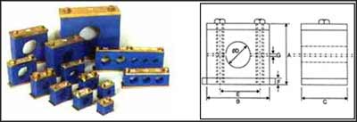
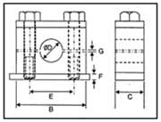
Pipe Clamps : |
|
|
| |
|
|
Normal Mechanical Stress |
|
Heavy Mechanical Stress |
| |
|
|
|
|
|
| |
|
|
19 |
97 |
113 |
45 |
60 |
90 |
4 |
2.5 |
PCS60 |
18 |
97 |
113 |
45 |
50 |
90 |
4 |
2.5 |
PCS50 |
17 |
97 |
113 |
45 |
48 |
90 |
4 |
2.5 |
PCS48 |
16 |
63 |
65 |
29 |
42 |
50 |
3 |
2.5 |
PCS42 |
15 |
63 |
65 |
29 |
38 |
50 |
3 |
2 |
PCS38 |
14 |
63 |
65 |
29 |
35 |
50 |
3 |
2 |
PCS35 |
13 |
63 |
65 |
29 |
33 |
50 |
3 |
2 |
PCS33 |
12 |
46 |
54 |
29 |
30 |
40 |
3 |
2 |
PCS30 |
11 |
46 |
54 |
29 |
28 |
40 |
3 |
1.5 |
PCS28 |
10 |
41 |
50 |
29 |
25 |
32 |
3 |
1.5 |
PCS25 |
9 |
41 |
50 |
29 |
22 |
32 |
3 |
1.2 |
PCS22 |
8 |
41 |
50 |
29 |
20 |
32 |
3 |
1.2 |
PCS20 |
7 |
39 |
40 |
29 |
18 |
25 |
3 |
1.2 |
PCS18 |
6 |
39 |
40 |
29 |
16 |
25 |
3 |
1.2 |
PCS16 |
5 |
39 |
40 |
29 |
14 |
25 |
3 |
0.9 |
PCS14 |
4 |
39 |
40 |
29 |
12 |
25 |
3 |
0.9 |
PCS12 |
3 |
31 |
34 |
29 |
10 |
19 |
3 |
0.9 |
PCS10 |
2 |
31 |
34 |
29 |
8 |
19 |
3 |
0.9 |
PCS8 |
1 |
31 |
34 |
29 |
6 |
19 |
3 |
0.9 |
PCS6 |
Sr.No. |
A |
B |
C |
D |
E |
F |
G |
Order Code |
|
|
18 |
148 |
190 |
65 |
90 |
140 |
12 |
3.7 |
PCH-90 |
17 |
148 |
190 |
65 |
75 |
140 |
12 |
3.7 |
PCH-75 |
16 |
97 |
113 |
45 |
60 |
90 |
10 |
2.5 |
PCH-60 |
15 |
97 |
113 |
45 |
50 |
90 |
10 |
2.5 |
PCH-50 |
14 |
97 |
113 |
45 |
48 |
90 |
6 |
2.5 |
PCH-48 |
13 |
70 |
80 |
29 |
42 |
57 |
6 |
2.5 |
PCH-42 |
12 |
70 |
80 |
29 |
38 |
57 |
6 |
2 |
PCH-38 |
11 |
70 |
80 |
29 |
35 |
57 |
6 |
2 |
PCH-35 |
10 |
70 |
80 |
29 |
33 |
57 |
6 |
2 |
PCH-33 |
9 |
70 |
80 |
29 |
30 |
57 |
6 |
2 |
PCH-30 |
8 |
59 |
68 |
29 |
28 |
43 |
6 |
1.5 |
PCH-28 |
7 |
59 |
68 |
29 |
25 |
43 |
6 |
1.5 |
PCH-25 |
6 |
59 |
68 |
29 |
22 |
43 |
6 |
1.2 |
PCH-22 |
5 |
59 |
68 |
29 |
20 |
43 |
6 |
1.2 |
PCH-20 |
4 |
59 |
68 |
29 |
18 |
43 |
6 |
1.2 |
PCH-18 |
3 |
42 |
53 |
29 |
16 |
32 |
6 |
1.2 |
PCH-16 |
2 |
42 |
53 |
29 |
12 |
32 |
6 |
0.9 |
PCH-12 |
1 |
42 |
53 |
29 |
10 |
32 |
6 |
0.9 |
PCH-10 |
Sr.No. |
A |
B |
C |
D |
E |
F |
G |
Order Code |
DIMENSION IN MM ARE FOR REFERENCE ONLY
|
|
| |
|
|
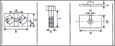
(Double) Tube Clamps |
|
|
| |
|
|
Clamp size |
Tube o. d.
Æ D1 Æ D2 |
2clamp halves
b c d e |
-Hexagon head-
d X L |
Weld plate g m |
1 |
6
6.4
8
9.5
10
12 |
6
6.4
8
9. 5
10
12 |
36 27 20 13.5 |
M6 X 35 |
37 M6 |
2 |
12.7
13.5
14
16
17.2
18 |
12.7
13.5
14
16
17.2
18 |
53 26 29 13 |
M8 X 35 |
55 M8 |
3 |
19
20
21.3
22
25 |
19
20
21.3
22
25 |
67 37 36 18.5 |
M8 X 45 |
70 M8 |
4 |
26.9
28
30 |
26.9
28
30 |
82 42 45 21 |
M8 X 50 |
85 M8 |
5 |
32
33.7
35
38
42 |
32
33.7
35
38
42 |
106 54 56 27 |
M8 X 60 |
110 M8 |
DIMENSION IN MM ARE FOR REFERENCE ONLY |
|
|
|
| |
|
|
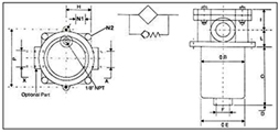
Return Line Filters / Tank Mounted : |
|
|
| |
|
|
|
|
|
| |
|
|
• Direct Tank Mounted Filter
• 10 Bar Working Pressure
• All Aluminium Die Cast Construction
• Optional clogging Indicator
• BSP Thread Standard- for Optional Threads Consult Factory
• For use with Mineral / Petroleum base oils
• 3 sizes - Flows to 120 LPM
• Bypass Standard - 1 Bar
• Elements Replaceable Through Cover
• Optional 10 & 25 Micron Paper Elements |
|
| Model No |
Port Size ABSP |
B |
C |
D |
E |
Port Size
FBSP |
H |
I |
L |
N1 |
N2 |
P |
Element Area 10/25 U Sq Cms |
| SM2-04 |
½" |
66 |
65 |
13 |
62 |
½" |
39 |
25 |
20 |
7.00 |
6.00 |
90 |
710 |
| SM2-06 |
¾" |
89 |
65 |
13 |
84 |
¾" |
51 |
42 |
33 |
7.00 |
8.00 |
114 |
1225 |
| SM2-08 |
1" |
89 |
120 |
13 |
84 |
¾" |
51 |
42 |
33 |
7.00 |
8.00 |
114 |
2450 |
| SM2-06-08 |
1" |
89 |
120 |
13 |
84 |
¾" |
51 |
42 |
33 |
7.00 |
8.00 |
114 |
2450 |
| DIMENSION IN MM ARE FOR REFERENCE ONLY |
|
|